

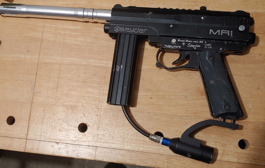
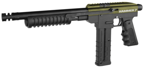
Recently, a teammate of mine purchased a gear bag deal that came with multiple markers, one being a well-loved Spyder MR1. But well-loved in this case didn’t translate to well taken care of; this Spyder has seen some things.
When my teammate, Eric (not his real name) attached a tank to it, air leaked down the barrel. He and another teammate did some basic maintenance by replacing the bolt and hammer o-rings, as well as re-lubing parts.
Having started with an MR1 way back when, I am pretty familiar with this marker. I still have mine lurking somewhere in my garage, in fact. When I mentioned that I used to run an MR1 to Eric, he handed me the marker and asked if I would be willing to take a look at it and see if I could fix it. My response was, “Sure, I’d be happy to help!”
Spyders are really simple markers. They are what’s called a “Stacked Tube Blow Back” design. The animation below is a pretty decent representation of how such a design works. One key difference between this animation an an MR1 is that the foregrip just hides the air-line, there’s no regulator. You’ll see this later in this article.
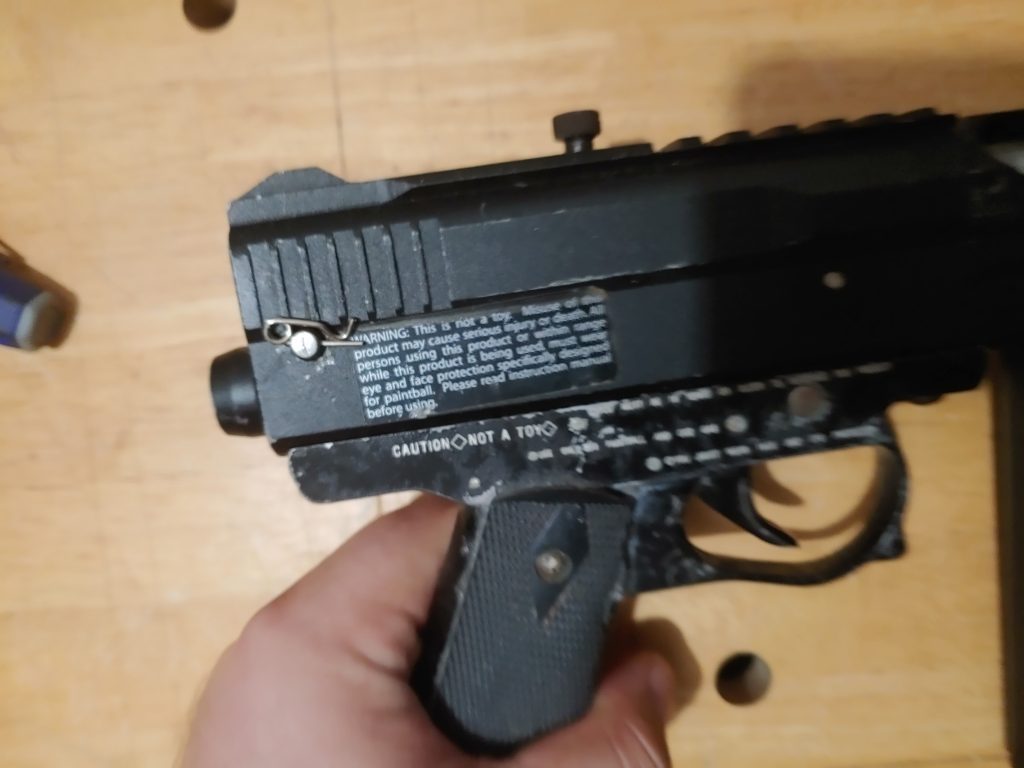
Before an allen wrench even touches this marker, there are a couple of things that stand out about this particular MR1 – the grip frame is not stock, but was pilfered from a Spyder TL. Additionally the drop-forward ASA is not the stock MR1 drop-forward ASA either. Not sure where it came from, but the screws used to secure the ASA to the grip are too long – they’re meant to thread through an ASA into the grip, like what you see on a Tippmann 98.
The grip is a non-issue, but the screws holding the ASA in place are. However, they can wait until later. Pulling the cocking pin out of the top of the marker will allow removal of the bolt and free up the hammer. Next, the grip and ASA need to be disconnected from the marker so I can remove the hammer from the lower tube.
There’s one last step before I free that hammer, though, and that is to remove the pin that holds the velocity adjuster and spring in place. On this particular MR1 the stock pin is replaced with a cotter pin, while not an ideal solution, it works.
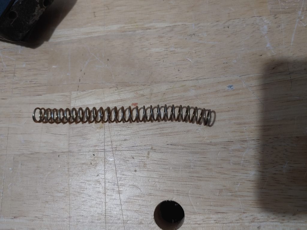
With the velocity adjuster and spring now free I was shocked to discover that the velocity spring had a bend in it. While not a show stopper, it’s not ideal to have a bent velocity spring. Thankfully I still had some replacement ones sitting around from my old MR1 and swapped one in as a replacement for this spring.
While the spring was wonky, the hammer looked to be in excellent condition – far better than the rest of the marker. The forward lip on the bottom of the hammer was still fairly square, which means it’ll catch the sear in the grip frame and stay. It’s not uncommon to see this forward lip be rounded down from continuous use. When that happens, the hammer doesn’t always stay on the trigger sear and will slip, resulting in misfires or the dreaded braaaaaap of a marker gone wild.
I didn’t get any good pictures of the bolt, but the bolt and its associated o-rings were looking good on account that my teammates had already replaced them in their earlier troubleshooting efforts.
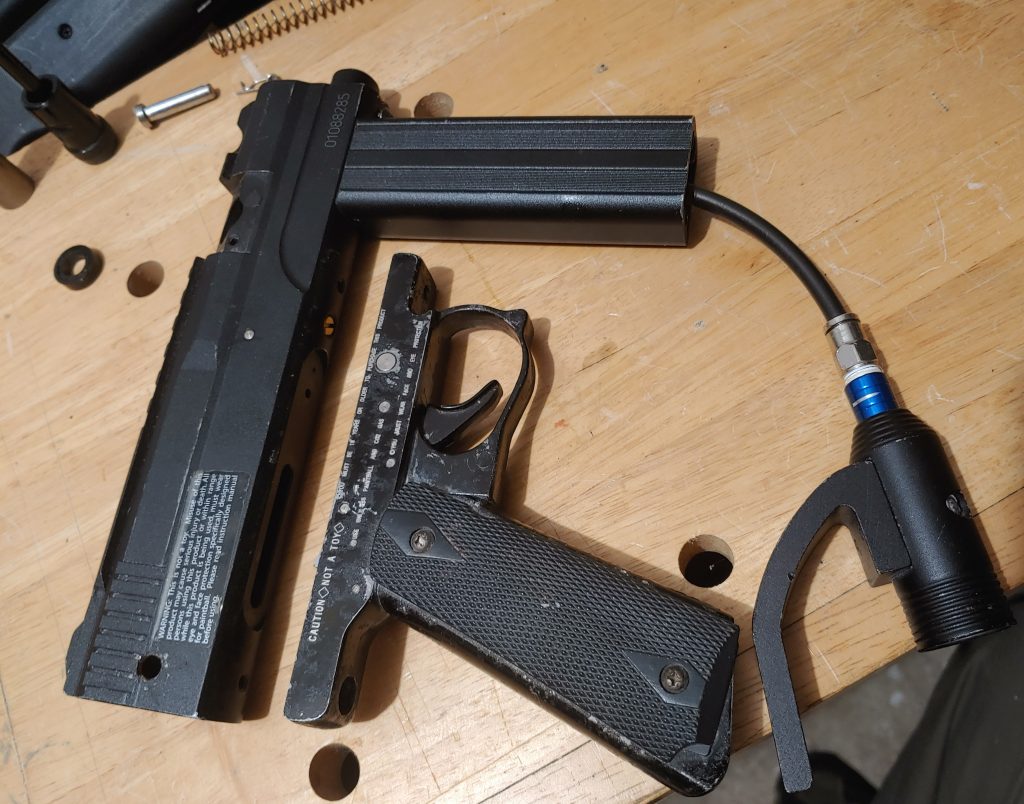
Next, the forward grip needed to come off. Easy as backing out these two screws.
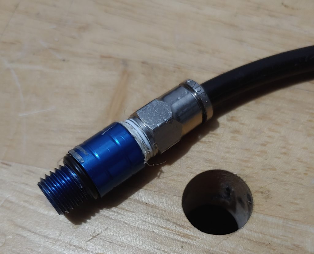
Oh, and it’s probably a good idea to disconnect the macro-line from the ASA so you can thread the grip off and out of your way. I recommend doing this as it makes it easier to disconnect the macro-line from the main body.
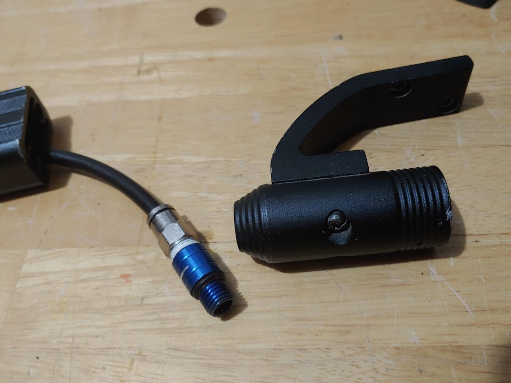
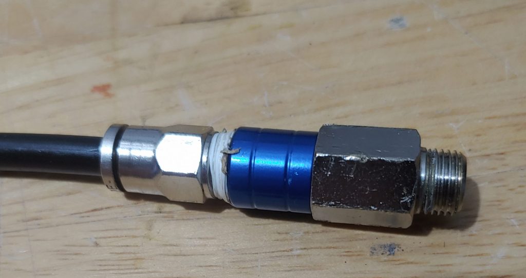
As mentioned earlier the foregrip isn’t hiding a regulator, just the macro-line and fitting that connect directly to the body. Removing the macro-line fitting here allows the remaining internals to be removed.
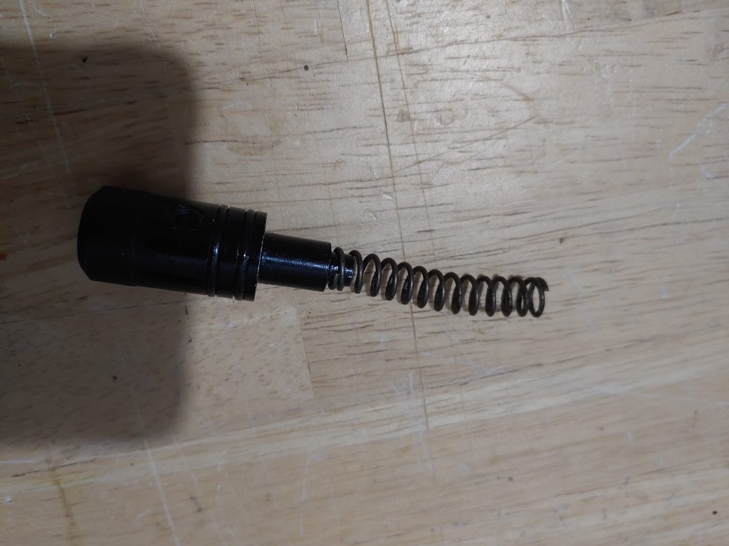
At the front of the block, just below the barrel is a pressure chamber plug with a valve spring connected to it. I was actually shocked to see that this valve spring was bent similarly to the velocity spring. However, unlike the velocity spring, I didn’t have a replacement on hand so it went back in like this.
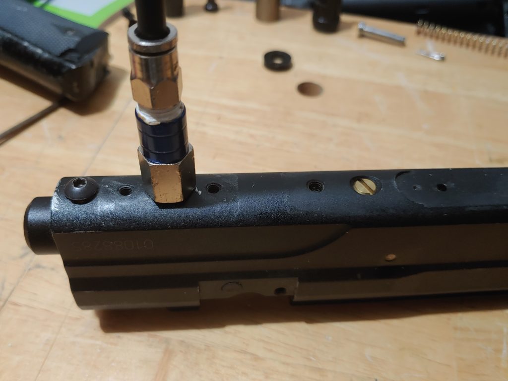
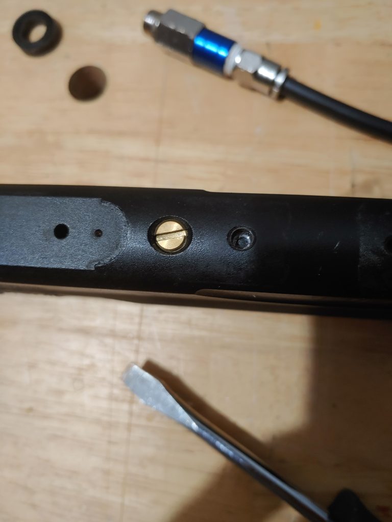
With all that out of the way, I could finally remove the main valve body. The brass screw in the picture below holds that valve body in place. Remove that screw and the valve body is ready to come out.
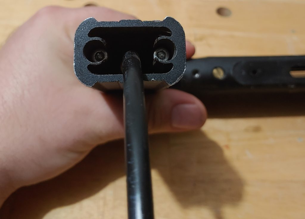
Removing the valve body from the marker is the fun part, need to get something long and skinny to shove down the back of the body to push it forward. There is a pin in the body that the valve sits up against so it can’t go backward, only forward.
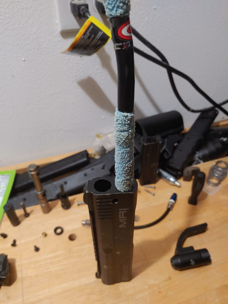
In this case, a barrel swab worked perfectly for the job, pulling double duty cleaning the lower tube while I was at it. Oh, and don’t mind the mess in the background – I have a couple of TCR’s I’m working on and had no where else to place all the magazines…
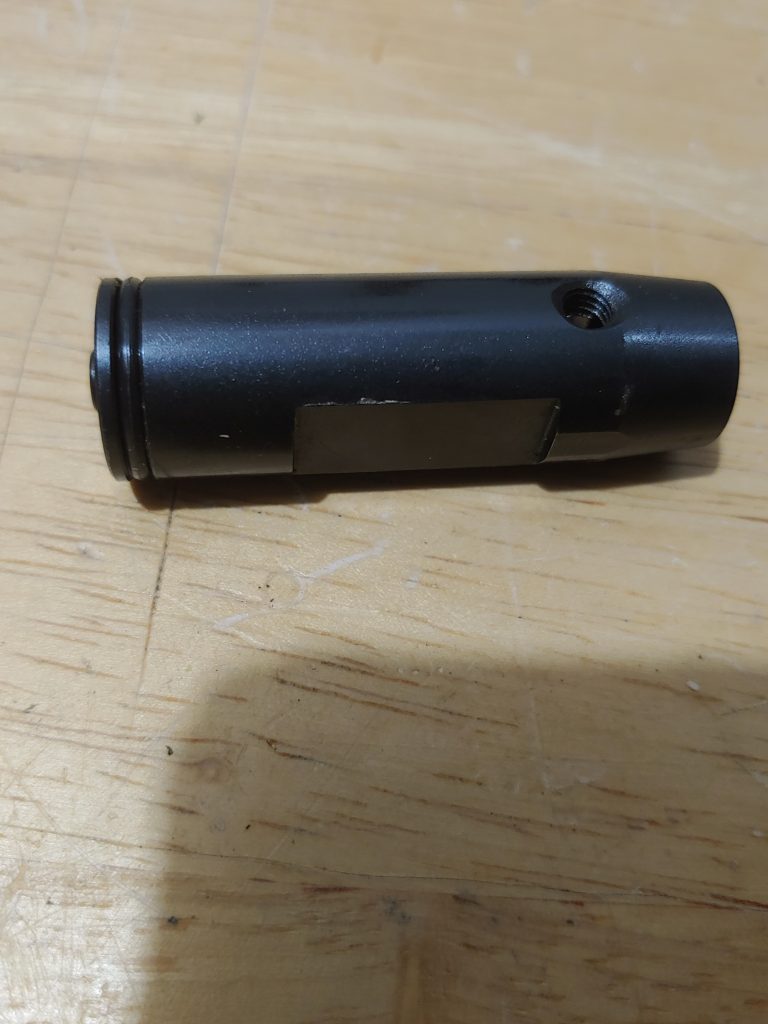
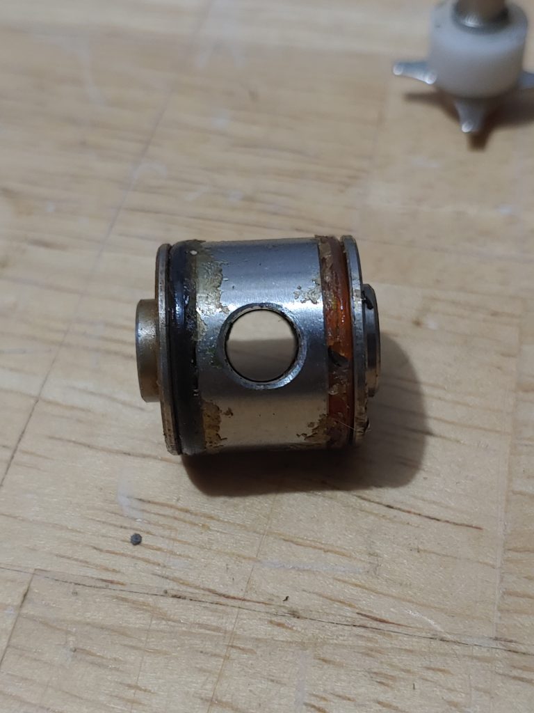
All that aside, I got the valve body out without issue and immediately saw the cause of all our woes: Rotten o-ring!
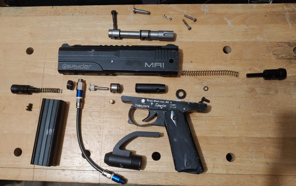
At this stage, the MR1 is completely disassembled.
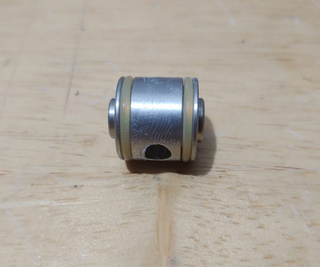
Not only is there a bad o-ring (and a highly suspect second o-ring), but the poor valve was gunked up with grease that was probably applied when my son was born nearly a decade ago. I removed the two o-rings and thoroughly cleaned the valve body, followed by a light coat of marker grease. Yes, grease and not oil! Oil doesn’t have the right properties to properly lube and seal the o-rings in the chamber. If you use oil, you’re going to have a bad time! With all that done, it cleans up pretty well, wouldn’t you say?
It’s critical that you pay attention to which way this valve body comes out of the marker because it has to go in the same way! If not, you’ll still have a leak down the barrel. I know, because I put it in backward and had to tear the whole thing back down to flip it around. To put the valve body back, use the same implement that you did to push it out. Pay attention to the direction of the holes on the side of the valve body, those holes are what the set screw secures to. Vertical orientation doesn’t matter, which hole goes up and which goes down – they both serve the same purpose.
As mentioned previously, I didn’t have a valve spring on hand, so that went back in as is. Before I reconnected the air-line, I had noticed in my test air-up that I had a leak coming out of one of the macro line connectors. I disconnected the macro lines from the connectors, wiped them down and reconnected them. The rest of the fittings looked to be in good order, so I left them alone.
Now, at this stage, I didn’t place the foregrip back on the body in case I had to disassemble the marker again, which did end up happening because I put the valve body in backward. Once I got the valve-body oriented correctly, the re-assembly went smoothly. The final thing to fix, though, was that poor loose ASA.
Before I tackled the ASA wanted to test and make sure that the marker was working correctly (again, my first attempt went awry) When I connected my test tank there was a little bit of a leak. This sometimes happens with a STBB. It’s a stupid simple fix: simply cock the bolt back and cycle it a few times by test firing. Doing this ensures that o-rings and the various parts settles into their final, operational, place. And for this MR1, that cycling did the trick! No more leak and it cycled like a champ!
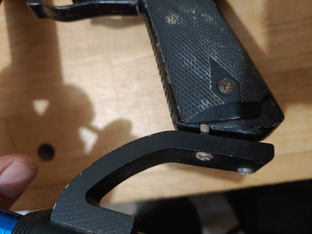
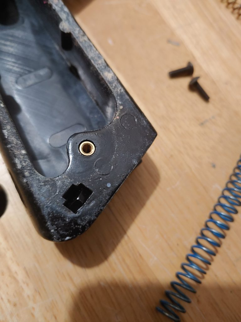
The final issue to address on this beat up old MR1 is the dropforward ASA mounting to the bottom of the grip. I had some metric nuts and bolts on hand for such occasions, so I grabbed a 4mm cap screw to test fit. The issue, though, was that the original nuts were a more coarse thread, so if these were going to work I would need to replace the nut, too.
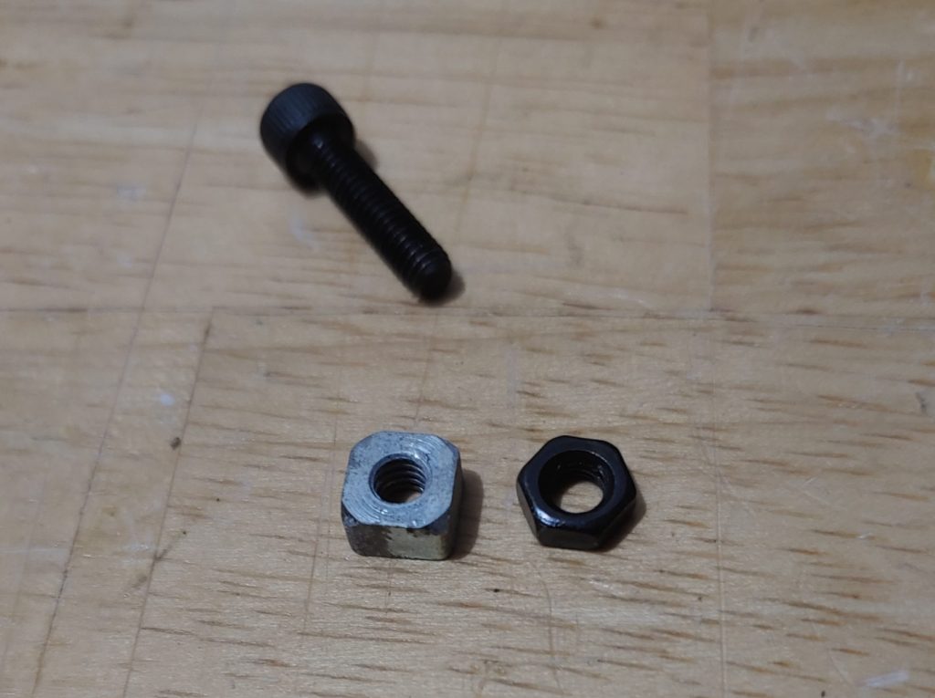
The original nut is designed to fit securely in a special slot in the grip frame.
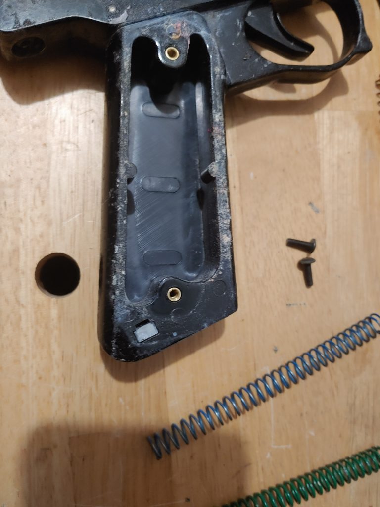
The replacement nut fit in pretty well, but not perfectly. Without the screw in place it has more room to rattle around. Additionally, the loose nut might prove to be a challenge to thread into.
I went with it anyway as it was an improvement over the previous configuration. I mounded the dropforward ASA and now it’s set solid with no movement.
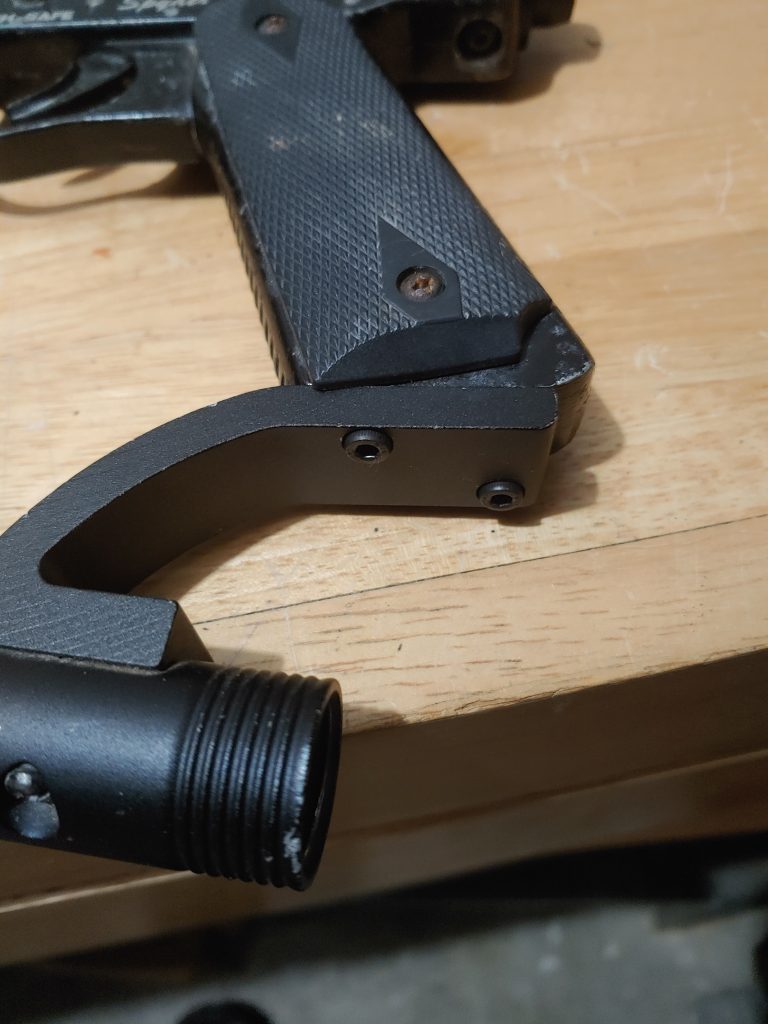
With the ASA firmly set, I connected a 48/3000 and drained it test firing this refreshed MR1. It cycled beautifully, though it kicked like a mule. I hand fed some paint into the chamber and this old MR1 was sending it down range like a champ.
Overall this repair took about an hour to complete. As you can see, MR1’s, and many Spyders by extension, are really basic markers. That was their beauty, and their bane. They are terribly inefficient, and there aren’t many options for mods and upgrades. But they are still great for handing over to a friend or family member as a loaner, or taking out onto the field just for the nostalgia factor!
